RTD PT100 sensor probe - Temperature Transmitter - Tibbit#43_1
Hardware Requirements:
TPP2-G2 board
Four-channel Streaming ADC ±10V Tibbit #43_1
Terminal Connector Tibbit #20
Power Tibbit #10 and #18
RTD PT100 sensor probe
Temperature Transmitter (Range of 0-10V)
Jumper Wires
Router for LAN
Software Requirements:
TPP2-G2 TiOS firmware (4.00.01)
TDST (Tibbo Device Server Toolkit)
TIDE (Tibbo Integrated Development Environment)
Device Explorer application preinstalled on your PC
In this article to test Tibbit #43_1, we are using an RTD PT100 sensor probe with 6.6 Feet (2 Meters) Length along with PT100 temperature transmitter DC24V with output in the range of 0-10V.
Tibbit#43_1 in single-ended mode has an input range of ±10V, due to which we have chosen the corresponding PT100 temperature transmitter range in 0-10V.
You can check more details on the single-ended and differential mode of Tibbit #43_1 on Tibbo's website here for a better understanding.
Choosing the right PT100 temperature transmitter:
You will get a lot of variations when you try to search for temperature transmitters online. so how to choose the correct transmitter for your project?
For me, it was simple to know as I was using Tibbit #43_1 which can understand the electric potential in terms of Voltage and NOT in current. While in the case of Tibbit#53 we need to use a different temperature transmitter that measures the electrical potential in terms of current (amperes) for which the range will be 4-20mA.
In the Online/Open market, you will find both the transmitter with voltage and current range but you need to check the specifications in more detail like the temperature measuring range is from 0-100°C or -50-150°C.
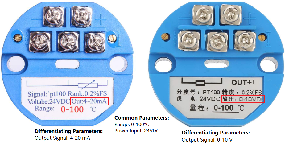
In the above snapshot, you will see both the temperature transmitter are almost the same but the main difference is the output signal in the current (4-20mA) and voltage (0-10V).
Here the common parameters are the measurement range which is the same 0-100°C and input power 24VDC.
In our current setup, we have Tibbit#43_1 and a transmitter with an output signal in the range of 0-10V and a temperature measurement range of 0-100°C, with this information one can know there is a linear relationship between the output signal and temperature, so if the temperature is 100°C you will get the output signal as 10V and at 0°C the output signal will be 0V.
The connection diagram of this particular transmitter is shown below for your reference. This will help you to understand the cabling with TPS and with third-party devices.
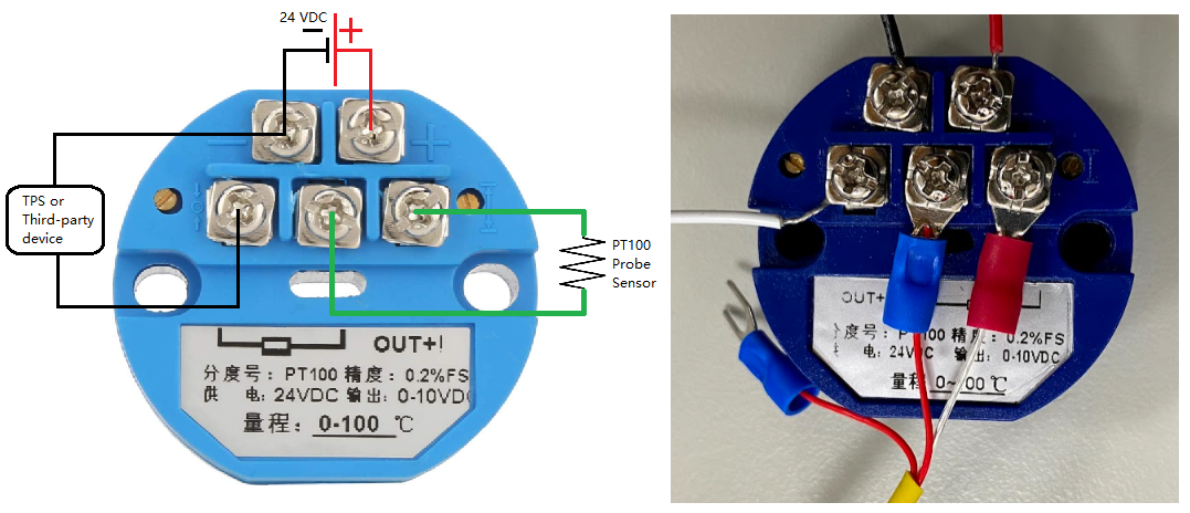
In the above comparison, you will observe that the WHITE cable on the left-hand side is going to TPS connecting it to Tibbit #43_1 and Ground is shared between the 24VDC and TPS.
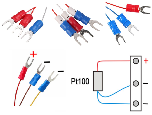
I had a PT100 probe sensor with three connectors and colour-coding of the cable are shared in the above snapshot, but you might have a different probe sensor with a different temperature measurement range and with different colour coding of the cables, so please check the manual (datasheet) of the respective manufacturer before connecting the cables.
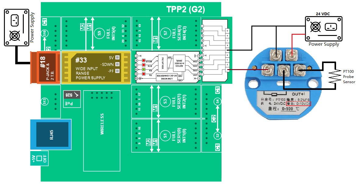
Please do check the Image below for the connection layout between the TPP2G2 board, RTD PT100 sensor probe and temperature transmitter.
CODY for Startup:
Generate the project using Cody by selecting the TPP2G2 board as your device and adding Tibbits #18, #10 for Power supply and Tibbits #43_1, #20 to collect the signal input from the PT100 probe sensor.
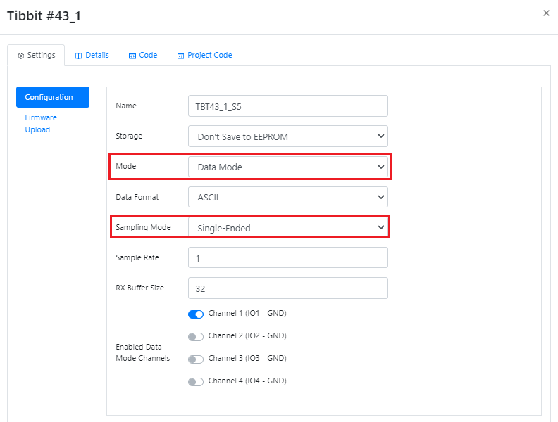
Change the "Mode" to "Data Mode", "Sampling Mode" to "Single-Ended", and "Channel" number for Tibbit #43_1 in CODY.
You can check more details on available modes, the sampling rate of Tibbit #43_1 on Tibbo's website here for better understanding.
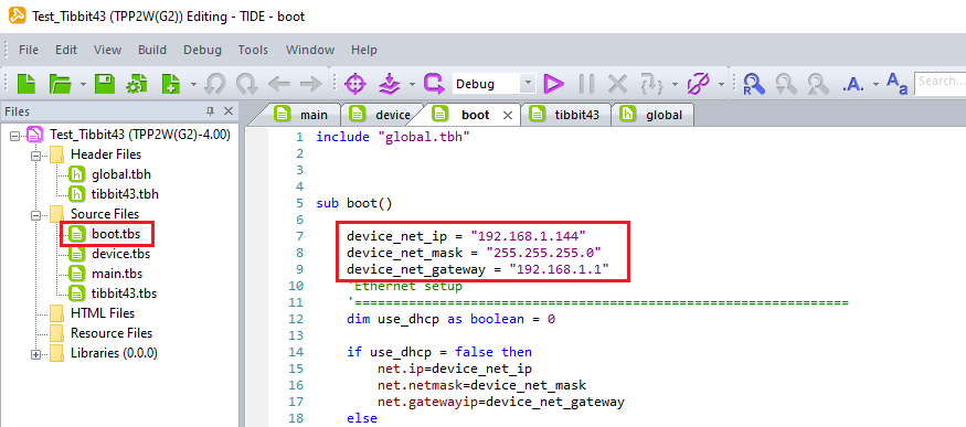
In the "Features" tab, enable the Ethernet feature and fill in the respective IP address, Subnet mask and Gateway address of your LAN network.
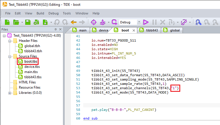
Download the project file to your computer, and if you want to make any changes to the TIDE project file, you can change the IP address and change the available ADC channels.
Connect the TPP2G2 board to the power supply and LAN network and compile the application to check for any errors.
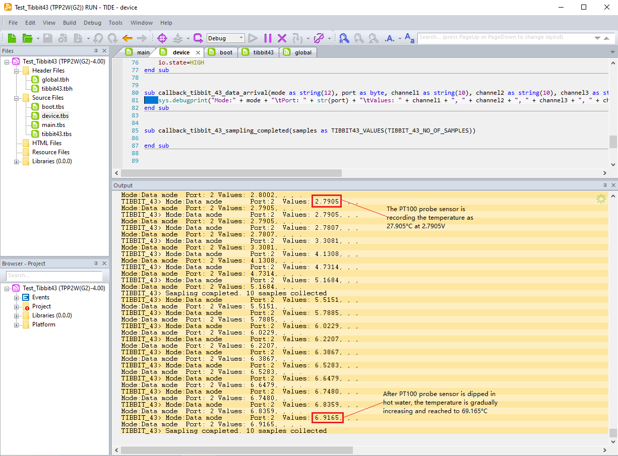
After compiling, select the target device (TPP2G2) and debug the signals on the available ADC channels.
The final results will appear like this.
Comments
0 comments
Please sign in to leave a comment.